


- Описание
- Комплект поставки
- Описание ПО
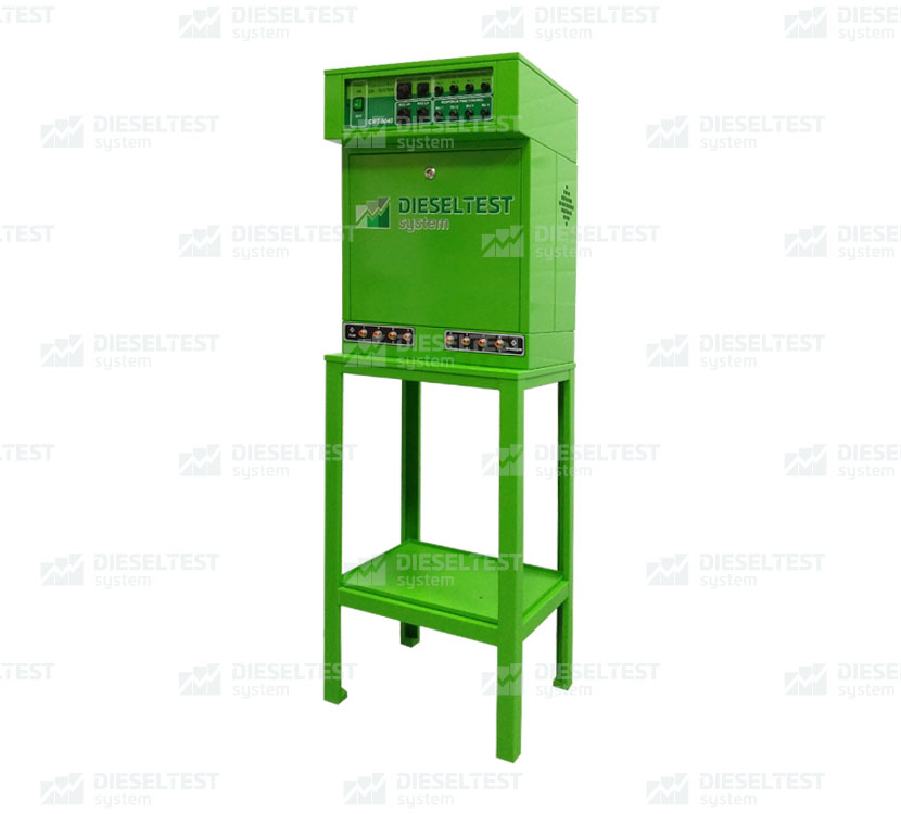
Flagman-Full. Комплект для испытания форсунок системы Common-Rail
Комплекс Flagman-Full предназначен для диагностирования форсунок системы Common-Rail производства фирм Bosch, Denso, Delphi, Siemens (VDO) на стенде. Проверка форсунок обеспечивается за счет подачи управляющего сигнала от контроллера на испытываемые форсунки и поддержания требуемого давления в системе согласно выбранному тест-плану.
Комплекс Flagman-Full имеет возможность дооснащения системой кодирования, в которую входит: система создания вакуума, состоящая из вакуумного насоса, электронного клапана, дроссельного регулятора и вакуумного манометра, а так же программного обеспечения CASCADE
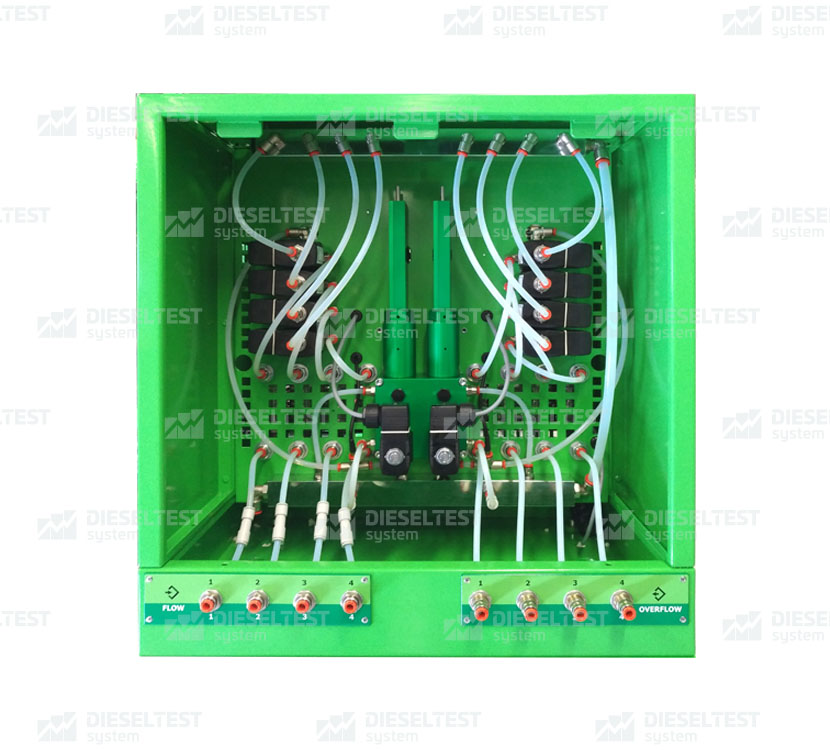
Измерительный блок разделен на 2 секции, предназначенные для измерения пролива тестовой жидкости через форсунки в магистралях «подачи» и «обратки» соответственно. Каждая секция может измерять пролив в 4-х каналах.
Все подключения подвода и отвода тестовой жидкости к элементам блока выполнены с использованием тефлоновых трубок (Ø 6мм) с помощью быстросъемных переходников. На входе в каждый измеритель установлен датчик температуры поступающей жидкости. Эта температура отображается в программе CASCADE.
Комплекс обеспечивает:
- Одновременное управление 1-4 форсунками
- *Возможность присвоения кода коррекции форсункам Bosch
- *Возможность присвоения кода коррекции форсункам Delphi
- *Возможность присвоения кода коррекции форсункам Denso
- Управление давлением в системе в ручном и автоматическом режиме
- Управление электромагнитными форсунками легковой серии с напряжения 14 В
- Управление электромагнитными форсунками грузовой серии с напряжения 28 В
- Управление пьезоэлектрическими форсунками
- Отключение управления в случае отсутствия защитного экрана в зоне испытания
- Управление останова привода стендового ТНВД после окончания теста
- Измерение температуры в баке
- Измерение температуры обратного слива форсунок
- *Измерение времени начала впрыска
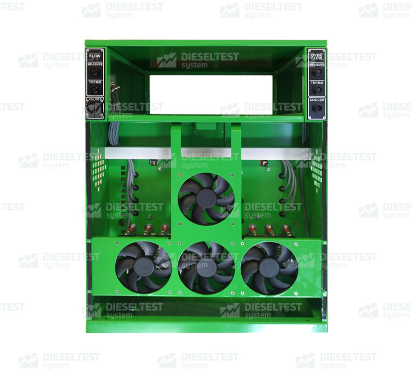
- Управление охладителем и нагревателем
- Управление измерением наливов подачи и обратного слива форсунок
*Функции являются дополнительными опциями и в базовую версию комплекса не входят!
Технические Характеристики |
|
| Количество одновременно проверяемых форсунок | 4 |
| Питание клапанов в измерительном блоке форсунок | 24 В |
| Частота подачи импульсов открытия форсунки | 60–1500 мин-1 |
| Длительность импульса открытия форсунки | 100–3000 мкс |
| Контроль температуры ТЖ для проверки форсунок | на каждой форсунке |
| Количество измерительных датчиков в МБ форсунок | 2 |
| Скорость измерения мерного блока форсунок | 0,01-0,5 л/мин |
| Погрешность измерения (легковые авто) 0,15-85 мм3 | не более 1% |
| Погрешность измерения (грузовые авто) 0,15-400 мм3 | не более 1,5% |
| Разрешающая способность МБ форсунок | ~0,1 мм3 /1 цикл (впрыск) |
| Комплект поставки Flagman-Full | |
| Наименование | Кол-во |
| Блок измерения безмензурочный MUFI-CR | 1 шт |
| Контроллер Flagman CRT-5040 | 1 шт |
| *Система создания вакуума | 1 к-т |
| *Датчик измерения начала впрыска | 1 шт |
| *ПО для кодирования DT-CODE Delohi | C2i, C3i |
| *ПО для кодирования DT-CODE Bosch | в разработке |
| *ПО для кодирования DT-CODE Denso | в разработке |
| Паспорт (тех. описание, инструкция по эксплуатации) | 1 шт |
| Комплект соединительных кабелей для блока измерения MUFI-CR и контроллера FLAGMAN | 1 к-т |
| Удлинитель для кабелей форсунок: гнездо «Injector» — 1.5м | 1 шт |
| Кабель-переходник для форсунок | 1 шт |
| Кабель-переходник для регуляторов высокого давления | 1 шт |
| Кабель-переходник для регуляторов низкого давления | 1 шт |
| Кабель-переходник для датчика давления | 1 шт |
| Кабель питания 220 В | 1 шт |
| Разъёмы для самостоятельного изготовления кабелей в гнёзда: «Protection»,»Tank t C»,»Reg t C», «Cycle», «Pump», «Invertor», «Rpm» | 1 к-т |
| Температурный датчик контроля температуры жидкости в баке: гнездо «Tank tоC» | 1 шт |
| Датчики температуры для измерения температуры обратного слива ТЖ | 4 шт |
| Герконовое реле для подключения защитного экрана: гнездо «Protection» | 1 шт |
| Предохранитель 3 А | 1 шт |
| Соединительные трубопроводы | 1 к-т |
| Совместимое оборудование и оснастка | |
| Накопитель давления на 1-3 регулятора | 1 шт |
| Регулятор давления 1-3 шт | 1-3 шт |
| Датчик давления | 1 шт |
| Предохранительный клапан | 1 шт |
| Манометр высокого давления | 1 шт |
| Держатель форсунок с кронштейном | 1 шт |
*Данные позиции являются дополнительными опциями и в базовую версию комплекса не входят!
Системные требования для ПК
Всё управление комплексом осуществляется с помощью программы «CASCADE»и персонального компьютера.
ПК должен удовлетворять следующим системным требованиям требованиям :
Минимальная конфигурация ПК:
- Процессор 1600 MHz и больше;
- Режим экрана 1024х768 (32 бита), рекомендуется 1280х1024
- Около 40 Мбайт дискового пространства для установки программы.
Программное обеспечение «CASCADE» позволяет проводить автоматизированное управление стендом.
С помощью программного обеспечения «CASCADE» подключается контроллер «CR—Injector-Tester». Контроллер «CR—Injector-Tester» предназначен для подачи программируемых сигналов управления регуляторами давления испытательной системы и форсунок системы CommonRail.
Основное окно-вкладка режима «CR-Injector-Tester»
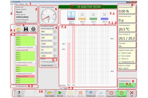
1.Меню
2.Вкладка выбора режима «CR-Injector-Tester»
Во вкладке режима «CR-Injector-Tester» располагаются:
3.Блок “Injector Info” (информация о форсунке)
4.Блок “Testplan” (тест-план)
4.1 Кнопки работы с файлами и вывода на печать: “Open”, “Save”, “Print report”
4.2 Поле для отображения этапов тест-плана (находится под кнопками 4.1)
4.3 Чек-бокс “Automatic test”
5. Блок манометра “Current pressure (bar)”
6. Блок параметров “Fuel Injection settings” (параметры впрыска топлива)
6.1 Поле “Pressure setpoint (bar)” – давление впрыска
7. Вкладка “Tester” – отображение виртуальных мензурок и параметров
8. Визуальные панели индикаций
9. Блок “Connected Devices” отображающий подключение устройств
10. Функциональные кнопки ПО «CASCADE» – F1…F12.
Есть возможность установить кодирование по дополнительному заказу.
Для кодирования форсунок необходимо получить результаты теста. Для этого надо выбрать из списка тест-планов интересующий нас тест по номеру форсунки Delphi. Открыть в режиме «Code with user target» или «Code with factory target». После окончания теста-плана можно посмотреть график и при необходимости улучшить результаты.
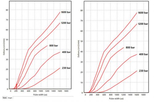
На графике слева не корректный результат. На графике справа корригированный результат.
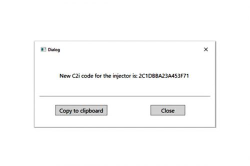
Для получения кода необходимо нажать кнопку “Get C2I code” в меню.
Если тест-план не доступен необходимо использовать любую новую форсунку из такой же группы «family», и воспользоваться режимом «Make user target»
Системные требования для компьютера:
- Процессор: Intel Core 3i или лучше
- 4 ГБ оперативной памяти (8 ГБ оперативной памяти с Windows 10)
- Жесткий диск SSD
- Windows 10